How Tight Are Our Cable Glands?

Mattia Rüegg
02. декабрь 2025
02. декабрь 2025

How do we ensure that our level probes function reliably even in demanding underwater environments? The tightness of the cable gland plays a crucial role. In this blog, I explain why it is so important and how I, as an apprentice, contributed to the further development of our testing device.
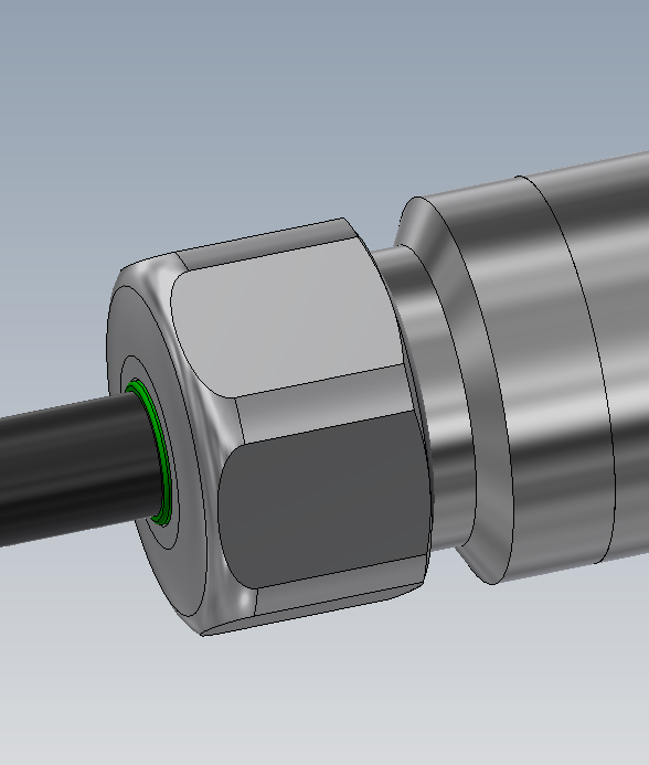
Structure and function of a cable gland
At first glance, the structure of a level probe resembles that of a transmitter. However, instead of a thread, a protective cap is attached to the membrane side. Another key difference lies in the electrical connection: while transmitters usually have an interface directly on the sensor, the level probe has a cable leading out of the interior of the housing. The challenge lies in ensuring a tight seal between the welded metal housing and the softer plastic cable. This is where the cable gland comes into play – an element that connects the two parts tightly and can withstand tensile forces at the same time.
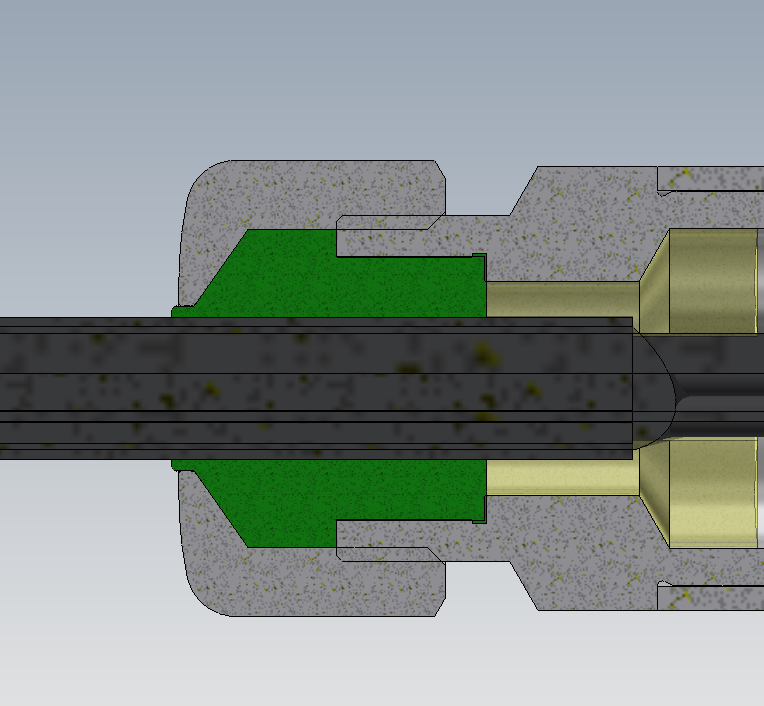
At KELLER Pressure, a cable gland developed in-house has proven itself, keeping the inside of the sensor dry with two barriers:
- The seal insert, which is pressed tightly against the housing wall using the pressure nut. (green)
- The grouting compound that fills the gaps and adheres tightly to the walls. (yellow)
The design requires a balance between tightness, mechanical strength and manufacturing costs.
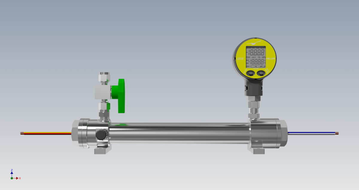
Device for leak testing
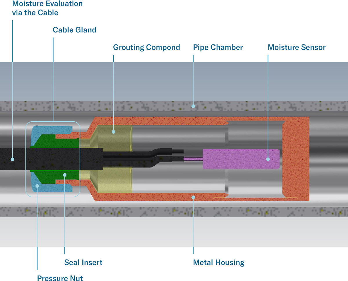
To guarantee functionality, the cable glands are tested using a special testing device. This measures the moisture inside the level probes. This allows any increase in leakage to be detected.
A specially prepared level probe is manufactured for this purpose. Instead of the usual electronics for pressure evaluation, it contains a moisture sensor inside. The level probe is enclosed in a pipe chamber with a pressure connection and pressure gauge. The electrical output of the prepared level probe is led out of the chamber via the cable. In this way, the moisture can be determined.
My task: Optimisation of the existing device
As a 3rd year apprentice design engineer, I was given the task of optimising our existing device. I followed the design process that I had learned during my training. First, I gained an overview of the situation. I analysed the existing device and recorded how it worked. I asked lots of questions to identify the ‘pain points’ for users and derive possible solutions. I wrote up a project documentation report containing all the information I had gathered and my findings.
After brainstorming ideas using research-based and intuitive methods, I sketched and designed variants in the form of 3D models. I compared the advantages and disadvantages to characterise the solutions and identify relevant differences. In consultation with my vocational trainer, I decided on the definitive solution variant and defined the exact implementations and dimensions. First, I analysed our internal manufacturing conditions, contacted various suppliers for the raw material and carried out calculations on strength and tolerances. Finally, all manufacturing documents were prepared and a final inspection was carried out.
The result was a lighter and corrosion-resistant device with simpler operating processes.
Lighter and corrosion-resistant device
Lessons learned from this exciting project
The project gave me the opportunity to learn more about cable glands and their application. Some of the tasks were not that easy. I made slow progress from brainstorming to the three final proposals. However, with the support of my vocational trainer, I was able to successfully complete all the steps.
At the end of the project, I reflected on the process and the methodology used: What went well and why? What were the risks and where were the mistakes? How should future projects be approached differently?
For me, it was a successful and very educational project, and I was able to gain a lot of experience. For me, every challenge is an opportunity to surpass myself. Learning never stops!
«The result was a lighter and corrosion-resistant device with simpler operating processes.»
Mattia Rüegg
Design Engineer in Training