Dynamics of Pressure Transmitters

Manuel Boller-Berger
03. сентябрь 2025
03. сентябрь 2025

Similar to the ever-increasing pace of everyday life, the demands placed on our pressure sensors and the medium to be measured are also evolving. Many applications require not only accurate but also fast measurements. In addition to measurement accuracy, the dynamic behaviour of the sensor is particularly important. Put simply, this refers to how long it takes for a change in pressure in the measuring medium to result in a change in the signal at the sensor output.
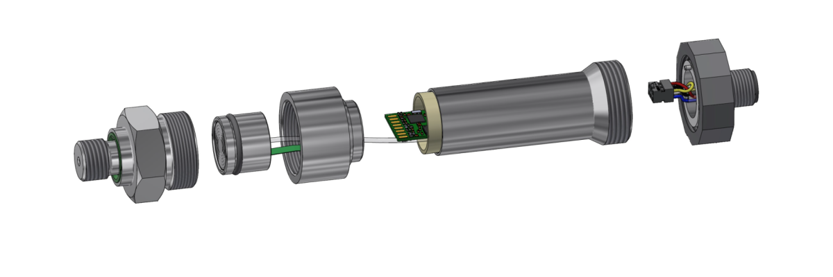
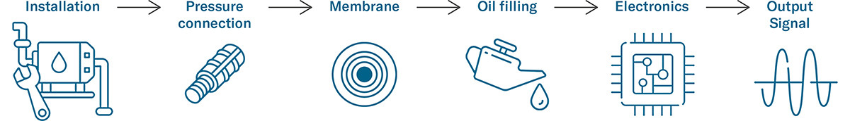
It is often assumed that the limiting frequency, sampling rate or similar parameters of the electronics are the decisive factors. In reality, however, this is only one aspect. In order to make a reliable assessment, the entire sensor system must be considered – from the pressure sensor head with the oil-filled pressure transducer capsule and the thread, to the middle section with the electronics, to the electrical interface. From the user's point of view, the pressure sensor is only one part of their overall system.
How fast does a sensor need to be, and what really influences its dynamics? In this blog, you will learn why it is not only the electronics but the entire sensor design that is crucial. I will show you typical applications where every millisecond counts, provide insight into test results, and help you find the right sensor for your requirements.
Parameters relating to the speed of pressure transmitters
Technical data sheets often refer to response time, bandwidth or sampling rate. However, these values are only meaningful if they are interpreted in the right context.
Various physical and technical parameters help to assess the dynamics of a pressure transmitter.
To understand the following terms, it is important to know the theoretical difference between analogue and digital, regardless of the specific electronics or output signals. Many terms cannot be compared directly as they do not exist for both types of signal or simply do not make sense.
Analogue vs. Digital
From the origin of the word, analogue means continuous and stepless. It stands for a value and time-continuous signal with any amount of numerical data with an infinite number of values, i.e. a very high dynamic range is possible.

Digital means countable. In mathematics, this refers to discrete, graded values (e.g. 0 and 1) as defined numbers with a finite number of values.

Parameters on the data sheet
Essentially, KELLER Pressure data sheets contain four dynamic specifications, which vary depending on the series.
1. Start-up time / Switch-on time
Describes the duration between the application of the supply voltage and the time from which the sensor supplies a valid output signal.
It is relevant for systems that are switched on and off to save energy. (Specified on the data sheet, typical time in relation to 0...99 %)

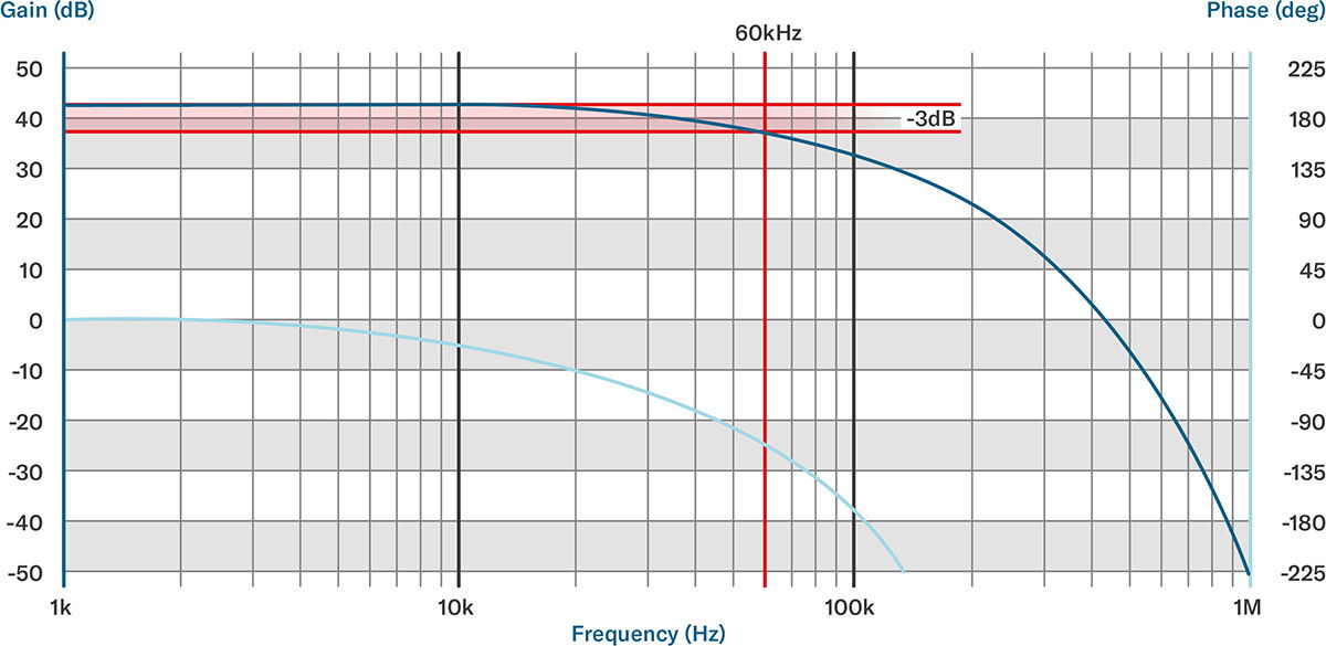
2. Limiting frequency / Bandwidth (fg = -3 dB-point) [Hz]
Specifies the frequency up to which pressure changes can be transmitted with a maximum attenuation of 3 dB (≈70 % of the amplitude). Above this frequency, the signal is increasingly attenuated. The system acts like a low-pass filter.
The bandwidth is a typical feature of analogue systems and should not be confused with the sampling rate of digital systems. Example: A piezoresistive sensor has a limiting frequency of > 10 kHz, the electronics (e.g. HB-Line) go up to 60 kHz, whereby the effective utilisation range can be significantly lower depending on the product.

3. Sampling rate (Sample Rate) [SPS, Hz]
Indicates how often a signal is recorded and processed internally per second. On our data sheets, this value can be found as «internal measuring rate» and is typically specified in Hz or SPS (samples per second).

Note: The limiting frequency is decisive for analogue outputs and the sampling rate for digital outputs.
The X-Line is particularly noteworthy as it supports both analogue and digital interfaces. Depending on the selected output signal, both values can be found on the data sheet.
4. Resonant frequency
The frequency at which the sensor system starts to oscillate. If the application is close to this frequency, unwanted oscillations, signal distortion or even mechanical overload can occur.
The resonant frequency depends largely on the mechanical structure, in particular the diaphragm, oil filling and pressure connection.
Further parameters
The following terms can be important for the dynamics of sensors, but are not explicitly stated on all data sheets.
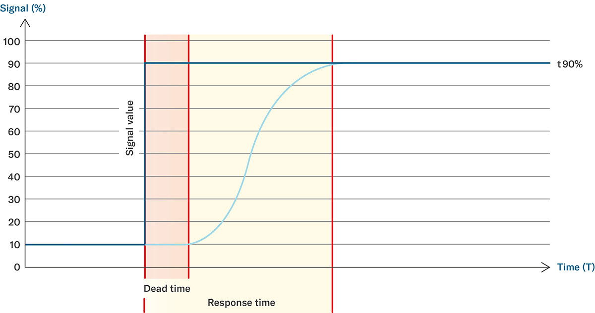
Response Time
Describes the time span (e.g. t63 or t90) that a sensor requires to reach a defined percentage of the final value (e.g. 63 %, 90 % or 99 %) after a pressure jump (a so-called step response).
For analogue sensors with «fast» electronics (e.g. HB-Elektronik), the response time is typically less than 10 µs. Digital systems such as the X-Line, on the other hand, require around 2 to 4 ms, depending on the selected output signal.
Dead time / Delay
Delay between a real pressure change at the input and the first recognisable reaction at the output. With purely analogue sensors, the dead time is negligible because measurements are taken in real time. With digital sensors, the dead time is part of the response time and is not specified as a single value.
Differentiation between sensor bandwidth vs. electronic sampling rate
With digital systems in particular, it is often assumed that a high sampling rate automatically means high dynamics. However, this assumption is only partially correct. The bandwidth of the sensor defines which pressure curves can be recorded at all, while the sampling rate indicates how often a signal is sampled, or rather recorded internally. A fast analogue-to-digital converter is useless if the mechanical components cannot keep up – and vice versa.
These terms describe how quickly and reliably a pressure transmitter can react to changes. However, they should always be considered in combination.
Typical applications with high demands on the measurement dynamics
In certain applications, the dynamics of the pressure transmitter play a central role.
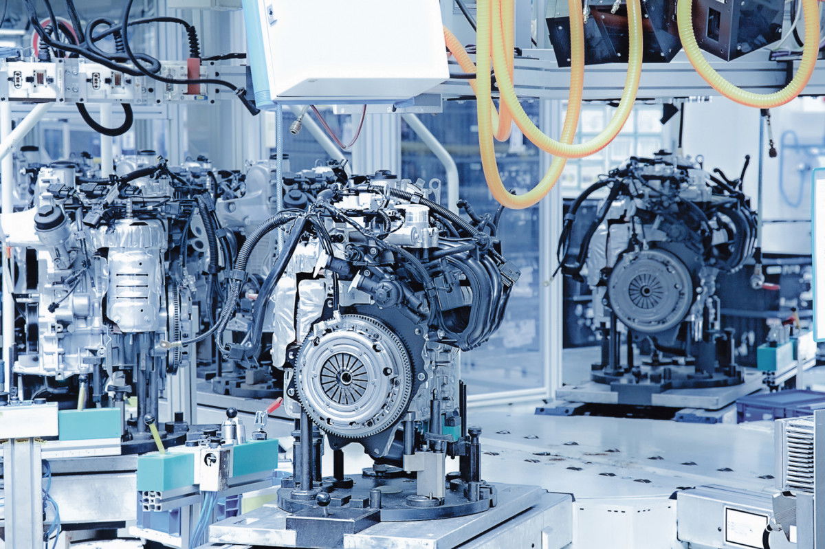
Hydraulic systems
In mobile and stationary hydraulic applications, fast pressure feedback is essential for load changes and valve movements. Analogue transmitters with a high bandwidth and minimal dead time are particularly in demand here. The shorter the dead time, the faster the sensor can provide feedback and control valves, for example. A dead time that is too long leads to delayed reactions or unstable behaviour of the control loop.
Our purely analogue and Y-Line products offer the necessary dynamics with bandwidths up to the kHz range. Their robust design and good venting options (e.g. flush-mounted with G1/4) make them particularly suitable for pulsating systems.
Products at a glance


Test bench technology
When characterising and testing pumps or valves, the pressure curve must be recorded in real time, including fast rise and fall times. With its analogue signal processing and bandwidths of up to 20 kHz, the HB-Line is ideal for these tasks. The high signal quality and low latency enable precise analysis of even short pressure peaks (more about this in our blog Pressure Peaks in Closed Systems). In combination with compact transducers, even complex test set-ups can be realised.
Especially in research or quality control (e.g. leak tests), the complete recording of a dynamic pressure curve is crucial. The sensors used must be able to deliver fast and low-noise signals.
Products at a glance

Hydrogen applications (H2)
During the refuelling process of H2 vehicles, high pressure increases and pressure peaks, known as transients, occur within a few seconds when refuelling starts or stops. Fast piezoresistive transmitters with a robust design are required to reliably detect these. Thanks to oil-filled pressure transducers and high measurement dynamics, safety functions and algorithms for fault detection can also be reliably implemented.
Products at a glance


Factors influencing the dynamics
In order to investigate what slows down our sensors, practical tests were carried out on various sensor setups with an external laboratory. The following points have a direct influence on the dynamics of our sensors:
Ventilation is crucial
The most important finding from the fluid tests: air bubbles in the system are the biggest killer of dynamics. With oil-filled systems in particular, even a small amount of residual air has a significant effect on the step response. Pressure transducers such as those in the M5 or a flush G1/4 process connection therefore showed particularly good results in those tests.
Electronics make the difference, but not alone
The comparison of two electronics (HB electronics with 60 kHz bandwidth vs. electronics with 1.2 kHz) clearly shows that the HB electronics can visualise high-frequency components in the pressure curve that are lost with the slower electronics. However, the electronics can only pass on what the sensor mechanically allows through.
How do you choose the right sensor?
When purchasing a sensor, a single data sheet value is rarely sufficient. Instead, a structured evaluation is worthwhile.
- What dynamics are actually required?
Is t90 = 10 ms sufficient or is a system response of < 1 ms required? - Where are the dynamic weaknesses in the planned structure?
Long lines, filter discs or viscous media can negate the advantages of a fast sensor. - What is more important: bandwidth or sampling rate?
With analogue outputs, the bandwidth or limiting frequency is what counts. With digital systems, the sampling rate is decisive, but only makes sense within the available bandwidth. - Which product line fulfils the system requirements?
For highly dynamic, analogue systems: purely analogue, HB-Line (e.g. M5HB)
For precise digital applications with a high sample rate: X-Line
For analogue applications with high bandwidth: Y-Line, C-Line
For simple applications with low dynamics: D-Line
Key messages at a glance
Understanding dynamics means understanding systems. The dynamics of a pressure transmitter are not a fixed property; they result from the interaction of many components. Although modern piezoresistive pressure sensors with optimised electronics (e.g. HB-Line) can offer very fast responses, the overall system is always the decisive factor:
Every link in this chain can limit the dynamics. In most cases, it is not the electronics, but the mechanical-fluidic coupling.
By correctly categorising terms such as bandwidth, sample rate, response time, dead time and step response, you can select the right sensor and avoid unexpected performance problems.
Поделиться
«It is often assumed that the limiting frequency, sampling rate or similar parameters of the electronics are the decisive factors. In reality, however, this is only one aspect.»
Manuel Boller-Berger
Technical Product Manager