Zone 0 Isn’t Always the Right Choice: Understanding ATEX Zones in Practice

Manuel Boller-Berger
09. April 2026
09. April 2026

Why explosion protection is an industrial reality
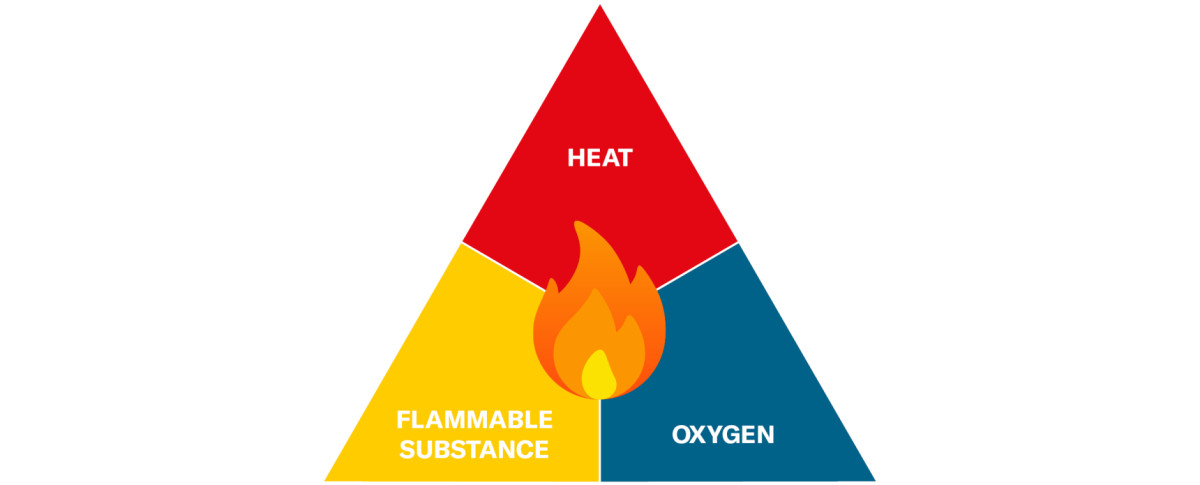
Potentially explosive atmospheres are not rather part of normal operations in many industrial applications. Wherever flammable gases, vapours, mists or dusts may be present, there is always a risk of explosion. (For a detailed explanation of what is required for an explosion to occur, please refer to the technical article ‘Explosion Protection in Pressure Measurement Technology’. Typical examples can be found in the chemical industry, in energy supply, in biogas plants or in the processing of solvents. More modern applications such as hydrogen infrastructure or gas distribution systems also fall within these areas.
However, when selecting suitable measurement technology, another question is particularly crucial: In which zone is the measurement point located?
Flammable gases and typical applications
Many industrial processes deliberately involve the use of flammable substances. Hydrogen, methane or various hydrocarbons, for example, are used as energy sources, process gases or chemical feedstocks. At the same time, explosive atmospheres can arise as a by-product of the process in numerous applications. This can be caused by evaporating solvents, atomised liquids or escaping gases.
Typical examples include:
- Hydrogen plants and H2 filling stations
- Gas compression and distribution
- Chemical processing plants
- Biogas and energy plants
In such environments, electrical equipment must be designed in such a way that it cannot itself act as an ignition source.
Pressure measurement in potentially explosive atmospheres
Pressure measurement plays a key role in these applications. Among other things, it is used to monitor tanks, pipelines, compressors and process reactors. Pressure transmitters are therefore often installed precisely in locations where explosive gas mixtures may be present.
In addition to measurement accuracy and long-term stability, it must be ensured that the device cannot cause ignition under any circumstances. Devices for potentially explosive atmospheres are therefore subject to specific guidelines, standards and approval procedures.
The key question: Which zone is actually involved?
When selecting a suitable device, it is not only the medium that is decisive, but above all the hazard zone in which the measuring point is installed. The classification into zones describes how frequently an explosive atmosphere may occur at a specific location.
In practice, a common misunderstanding arises here: if a flammable gas is used, the highest hazard class is automatically assumed. In reality, however, industrial plants vary greatly in terms of how frequently an explosive atmosphere may occur.
For example, while an explosive mixture may be present continuously inside a tank, in well-ventilated pipework areas it often occurs only rarely or only in the event of a malfunction. It is precisely for this reason that the ATEX system distinguishes between Zones 0, 1 and 2.
The correct classification of the measuring point is therefore crucial for selecting suitable pressure measurement technology.
ATEX zones: The basic principle
Potentially explosive atmospheres are not defined solely by the presence of a flammable substance, but by the likelihood of an explosive atmosphere occurring. On this basis, industrial plants are classified into different hazard zones.
The classification is carried out as part of a risk assessment by the plant operator or designer. Factors such as the likelihood of leakage, ventilation, process conditions or mode of operation play a decisive role in this.
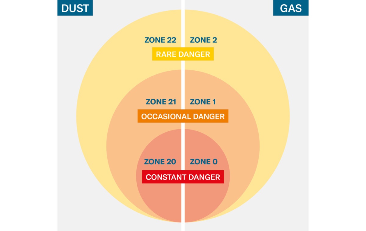
Zone 0
Describes areas where an explosive atmosphere is present continuously, for long periods or frequently. Typical examples include the interiors of tanks, vessels or process reactors in which a flammable gas is present at all times.
Zone 1
Refers to areas where an explosive atmosphere may occasionally occur during normal operation. This may be the case, for example, near valves, compressors or potential leak points.
Zone 2
Covers areas where an explosive atmosphere does not normally occur during normal operation and, if it does arise, is only present for a short time. These are often well-ventilated areas of plants or the periphery of pipework.
Important: The zone classification describes the environment, not the equipment. It is only on this basis that the protection concepts permitted for electrical equipment are determined.
Relationship between zones and equipment categories
For Zone 0, protection concepts are generally used which can reliably prevent ignition even in the event of a fault, for example intrinsically safe equipment.
In Zone 1, other protection principles may also be used, such as products with flameproof enclosures, which safely contain any potential explosion within the equipment.
For Zone 2, protection concepts are used which do not create any ignition sources during normal operation and are designed to prevent sparking or excessive heating.
The correct assignment between zone and equipment category is therefore crucial for safe and, at the same time, cost-effective system planning:
Zone 0 => Category 1
Zone 1 => Category 1 or 2
Zone 2 => Category 1, 2 or 3
Practical example: H2 filling station
The zoning becomes particularly clear when viewed in the context of a specific installation. Hydrogen filling stations are well suited for this, as they involve various process steps while working with a highly flammable gas.
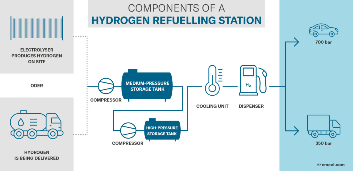
A typical H2 refuelling station consists of several functional areas: storage, compression, intermediate storage and dispensing to the vehicle. In each of these areas, different conditions for the formation of an explosive atmosphere may exist.
Functional areas of a plant
A hydrogen refuelling station generally comprises the following main components:
- Storage tanks for compressed hydrogen
- Compressors that bring the hydrogen up to the required pressure
- High-pressure storage tanks or buffer systems
- Piping and valves for distributing the gas
- Dispensers for refuelling vehicles
In all these areas, the process pressure is monitored, which is why pressure transmitters are used at various points within the plant.
Typical zone classification
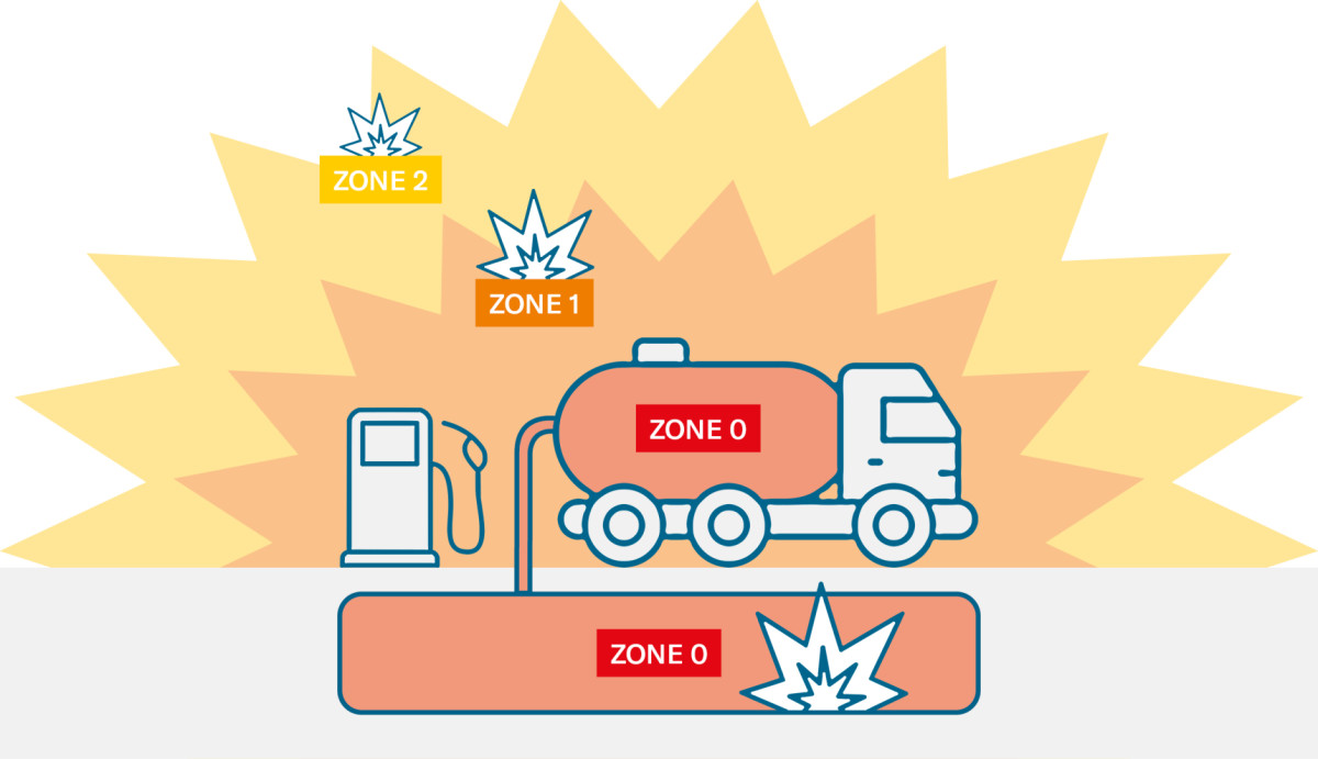
A flammable gas mixture is permanently present inside a hydrogen tank. This area is therefore usually classified as Zone 0.
In areas with potential leakage sources, such as compressors, valves or fittings, hydrogen may occasionally escape during normal operation. These areas are frequently classified as Zone 1.
However, a large part of the plant is located outside these immediate leakage points. Pipework, measuring points or plant components in well-ventilated areas are therefore often classified as Zone 2.
Implications for pressure measurement technology
For pressure measurement technology, this means that very different explosion protection requirements may apply within the same plant.
- Measurement pointsinside tanks or vessels are typically located in Zone 0.
- Measurement pointsnear compressors or valves are often located in Zone 1.
- Measurement points in pipework or in well-ventilated areas are often classified as Zone 2.
Particularly in complex plants, it is evident that a large proportion of measuring points do not fall within the highest hazard class. A precise analysis therefore enables explosion protection that is both technically appropriate and efficient.
Comparison of protection concepts
Depending on the zone classification, different protection concepts are used for electrical equipment.
Ex ia: Energy limitation and barrier
With the intrinsic safety (Ex ia) type of protection, the electrical energy in the circuit is limited to such an extent that ignition cannot occur even in the event of a fault, no ignition-capable sparks or hot surfaces can be generated.
To achieve this, the entire measuring circuit is energetically limited. Safety barriers or isolating amplifiers are typically used for this purpose.
Typical features:
- Energy limitation throughout the entire circuit
- Additional components such as barriers or isolating amplifiers
- High demands on planning and documentation
Ex db: Pressure-resistant enclosure
Another protection principle involves enclosing potential ignition sources within a robust housing. Should an explosion occur inside the device, it must not be allowed to escape to the outside.
Typical features:
- Solid housing to withstand potential explosion pressures
- No additional barrier required in the circuit
- Robust construction
Ex ec: Design-based prevention of ignition sources
The increased safety (Ex ec) type of protection takes a different approach. The aim is to prevent the formation of potential ignition sources even during normal operation. To this end, the device is designed in such a way that sparking, high surface temperatures or other potential ignition mechanisms are ruled out.
Typical features:
- Design-based prevention of sparking
- Limitation of surface temperature
- No additional energy limitation required in the circuit
- More compact design compared to flameproof enclosure
Positioning within the portfolio
The various protection concepts are also reflected in the product portfolio for potentially explosive atmospheres. Different device concepts are used depending on the hazard zone and plant requirements.
It is therefore important for operators and plant designers that a portfolio covers several protection principles in order to provide suitable solutions for different installation conditions.
Zone 0: intrinsically safe variants (Ex ia)
For applications with a permanently present explosive atmosphere, such as inside tanks or process vessels.
Intrinsically safe pressure transmitters


Zone 1: Flameproof enclosure (Ex db)
Robust devices that contain a potential explosion within the housing and can be operated without energy limitation in the circuit.
Pressure transmitters with flameproof enclosure


Zone 2: Increased safety (Ex ec)
In addition to applications with higher hazard levels, there are a large number of measuring points in Zone 2 areas within industrial plants. For such applications, devices with the Ex ec ignition protection type can be used.
With the Zone 2 approval of the Y-Line, the portfolio is expanded to include a solution specifically designed for these common applications.
Pressure Transmitters for Increased Safety


What Zone 2 changes in practice
The zone classification of a measuring point affects not only the device used, but the entire measuring system.
These differences primarily affect the planning, installation and operation of the measurement technology.
Elimination of the barrier
In intrinsically safe measurement systems, the energy in the entire circuit must be limited. To achieve this, safety barriers or isolating amplifiers are used, which are installed between the measuring instrument and the control system. These components are located in the safe area and ensure that no ignition-capable energy can arise in the potentially explosive atmosphere.
In Zone 2 applications with devices of the Ex ec protection type, such energy limitation is generally not required. The measuring instrument can be connected directly to the evaluation electronics or control system.
Reduced installation effort
Intrinsically safe systems require a detailed design of the entire circuit, including cable lengths, capacitances and inductances.
In Zone 2 installations using appropriately approved devices, a large part of these requirements is eliminated. The installation is more similar to that in non-hazardous areas, which significantly simplifies planning and assembly.
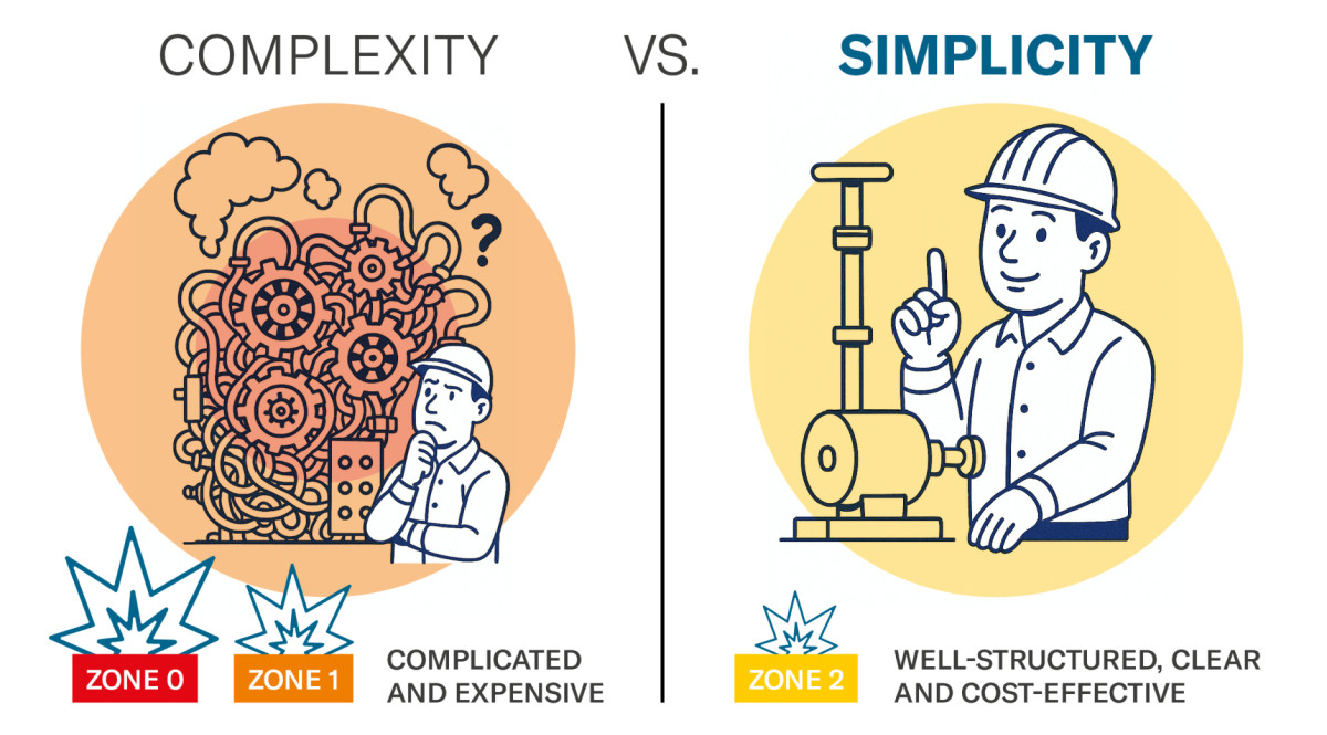
Lower system complexity
Avoiding the need for additional components reduces wiring, control cabinet space requirements and potential sources of error. This effect can be particularly noticeable in larger plants with many measurement points. Every additional component generally increases the effort required for planning, installation and maintenance.
Economic implications
In addition to the technical advantages, reduced system complexity also has economic implications. The elimination of additional components such as barriers reduces not only material costs but also the effort required for planning, installation and commissioning.
Furthermore, a simpler system structure can also facilitate maintenance. Fewer components generally mean fewer potential points of failure and easier troubleshooting during operation.
For plant operators and integrators, correct zone classification is therefore not only a matter of safety, but also a key factor in the efficient and cost-effective implementation of measurement systems.
Conclusion
The selection of suitable pressure measurement technology does not begin with the instrument, but with the correct zone classification of the measurement point.
While particularly high requirements apply to applications in Zone 0 or Zone 1, a large proportion of industrial measuring points are actually located in Zone 2 areas. Here, devices can be used which are designed to prevent ignition sources without requiring additional energy limitation in the circuit.
The elimination of safety barriers simplifies the planning, installation and documentation of the measuring system whilst simultaneously reducing system complexity.
Precise zone classification therefore enables explosion protection to be implemented both safely and efficiently, and allows the appropriate solution to be selected for the actual conditions in the plant.
Manuel Boller-Berger
Technical Product Manager